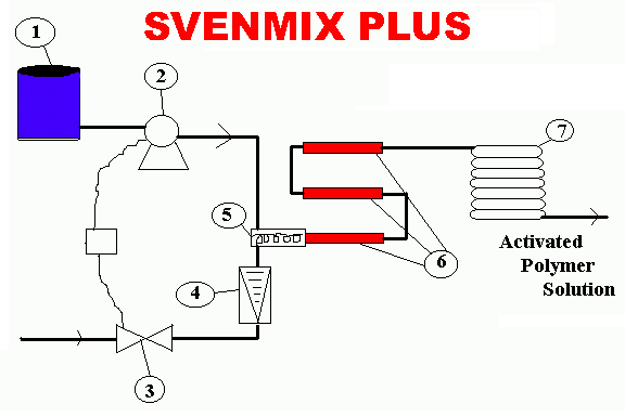
Process Diagram
|
1. Calibrated Polymer Reservoir. Reservoir provides suction to the Polymer pump
which eliminates priming problems 2. Polymer Pump has 100% - 0 turn down for maximum capacity. The Polymer Pump injects the polymer into a mixing tee in front of the Primary Mixing Section. 3. Dilution water flows through a Solenoid valve which flows into a flowmeter 4. The flowmeter measures and controls the amount of dilution water through the system 5. The Mixing Tee brings both the dilution water and the polymer together and outlets into the primary Mixing Section. It also helps eliminate the formation of "fish eyes" 6. The polymer and dilution water are blended and Mixed through three static mixing sections. 7. The Homogenization section ages the polymer solution and the result is an activated polymer solution |


